This guide summarizes high-frequency faults in daily BMS battery management system O&M, organized into four categories: Master Control & Communication, Insulation & Current Detection, Temperature & Voltage Acquisition, and Charging Faults. Each fault is optimized with causes and troubleshooting steps in plain, easy-to-understand language with clear procedures, suitable for equipment O&M and maintenance personnel.
Fault codes in this manual are for reference only. Codes may vary slightly between different manufacturers' BMS equipment.
Before any electrical testing and line disassembly, be sure to de-energize and take safety precautions. High-risk operations should be performed by qualified professionals.
If the fault persists after troubleshooting following this guide, contact the equipment manufacturer's technical support.
These faults mainly involve the equipment master control unit, signal lines, and communication module abnormalities, which can cause equipment non-operation and complete communication failure.
Fault Phenomenon | Fault Code | Fault Cause | Troubleshooting Steps |
BSU (Master Controller) Not Working | None | 1. Abnormal 24V operating voltage — equipment power supply fault | 1. Measure BSU master controller 24V operating voltage; confirm stable power supply |
BMS Cannot Communicate with Vehicle | BMS Communication Fault | 1. CAN communication line loose, broken, or abnormal connection | Same as BSU not working; prioritize CAN communication line troubleshooting, then replace vehicle protocol box |
Acquisition Module Communication Fault | EC-X | 1. Abnormal 24V operating voltage to acquisition module | 1. Measure 24V DC supply voltage; repair power supply fault |
Insulation Module Communication Fault | CRU-E | 1. Abnormal 24V DC supply to insulation module — module did not start | 1. Measure insulation module 24V supply voltage; troubleshoot power supply lines |
Communication Normal but Battery Pack Indicator Light Off | None | 1. CAN communication signal lines reversed (+/-) | 1. Verify CAN line wiring sequence; correct reversed lines |
These faults mainly affect battery insulation performance and current data acquisition, easily causing inaccurate data, equipment leakage, and detection anomalies.
Fault Phenomenon | Fault Code | Fault Cause | Troubleshooting Steps |
Insulation Detection Anomaly | CRU-F | 1. Battery pack relay not properly closed | 1. Measure battery pack voltage; check if it is standard pack voltage; troubleshoot relay fault |
Current Data Displayed Inaccurately | IO-H, IC-H | 1. Insulation module damaged — data acquisition failed | 1. With equipment in static state, unplug Hall line; normal reference current is ~90A; deviation indicates insulation module damage — replace |
Charge/Discharge Current Polarity Displayed Opposite | None | 1. Hall detection lines reversed | 1. Adjust Hall sensor line installation direction |
Equipment Leakage | R-E | External vehicle device leakage (inverter, generator, air pump, etc.) or battery body leakage | Sequentially disconnect high-voltage input of inverter, air pump, and other external devices to find the leakage source. If fault persists after disconnecting external devices, it is determined as battery body leakage |
These faults involve battery temperature and cell voltage acquisition anomalies, triggering over-temperature, excessive voltage differential, and wire break alarms, affecting normal battery operation.
Fault Phenomenon | Fault Code | Fault Cause | Troubleshooting Steps |
Battery Over-Temperature Alarm | TEMP-HX | 1. Temperature sensing probe damaged or failed | 1. Verify actual battery temperature; normal temperature probe resistance is ~8kΩ at room temp; abnormal value indicates probe needs replacement |
Excessive Battery Voltage Differential Alarm | ULH-OV | 1. Actual battery cell voltage is low | 1. Measure actual cell voltage; check if battery has under-voltage |
Acquisition Wire Break Alarm | LBK-X | 1. Battery cell voltage too low — below 200mV | 1. Measure actual cell voltage; troubleshoot battery under-voltage fault |
These faults cause the equipment to be unable to charge normally, mostly caused by communication abnormalities, battery faults, or line/component faults.
Fault Phenomenon | Fault Code | Fault Cause | Troubleshooting Steps |
Equipment Cannot Charge | None | 1. Communication interruption between charger and BMS system | 1. Check CAN communication lines between charger and BMS; repair line faults |
Code Compatibility: All fault codes in this document are for general reference only. Codes vary between different brands and models of BMS equipment. Use equipment manuals for reference during troubleshooting.
Safety Operation: High-voltage electrical equipment maintenance carries safety risks. All wiring testing and component replacement must be done with power off. Non-professionals are prohibited from disassembling equipment.
After-Sales Support: If the fault is not eliminated after completing all troubleshooting steps above, do not modify the equipment privately. Contact the manufacturer's technical personnel for on-site repair.
 Wow! The main power storage battery for the Shenzhou-19 manned spacecraft is a lithium battery!March 31, 2026Introduction:Starting with Shenzhou-18, the main power storage batteries of the Shenzhou spacecraft have been upgraded to more advanced lithium-ion batteries, with each battery pack's capacity inc...view
 Low & High Voltage Ride-Through: Why They Are Essential Stabilization Requirements for New Energy EquipmentJuly 22, 2026As large-scale PV and wind power connect to the grid, new energy sources are gradually replacing traditional generation, becoming the primary power supply unit of the power system. The grid is like a ...view
 Golf Cart Battery Pack Upgrades (2026): How Lithium Helps Resorts and Courses Go Greener — And Look Better Doing ItJune 16, 2026For modern resorts and golf courses, sustainability is no longer a nice-to-have. Environmental compliance pressure is rising across hospitality and leisure sectors, and brand reputation increasingly d...viewUnderstanding Grid-Forming Energy Storage: The Ultimate Stabilizer for New Energy Power GridsJuly 22, 2026In the new energy era, the power grid lacks a 'critical short board.' Wind and PV power stations are now everywhere, gradually replacing traditional thermal and hydropower, helping the power i...view
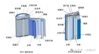 Safety First: A Multidimensional Strategy Analysis for Enhancing Lithium-ion Battery SafetyMarch 31, 2026Application and Safety Issues of Lithium-ion Batteries: Lithium-ion batteries are widely used due to their high energy density, high output power, and high average output voltage. However, accidents ...view
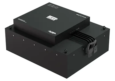 Uniformity of Lithium Battery Coating and Its Impact on Lithium BatteriesMarch 31, 2026Abstract: This paper delves into the issues of uniformity in lithium battery coating, its impact on battery performance, and the corresponding solutions. By analyzing each step in the coating process,...view
 EN
EN