At energy storage industry exhibitions, a disruptive high-voltage energy storage product has consistently stood out, becoming a focal point for the entire industry. Its most critical breakthrough is the complete elimination of the traditional line-frequency step-up transformer required in conventional high-voltage energy storage systems, fundamentally reshaping the grid interconnection architecture that has been in use for decades.
Traditional line-frequency transformers are bulky and weigh several tons. They not only occupy valuable space at the power station, but also introduce inherent operational losses, driving up project construction and O&M costs. It is precisely for these reasons that industry giants such as CATL, Huawei, and Sungrow have heavily invested in high-voltage cascaded energy storage technology, precisely addressing the numerous pain points of traditional solutions.
How does high-voltage energy storage achieve stable grid connection without a transformer? What exactly makes this new technology superior? This article uses plain language and progressive logic to comprehensively deconstruct the core principles, operating mechanisms, and competitive strengths of high-voltage cascaded energy storage.
In the current field of high-voltage, high-power energy storage, the Three-Phase Cascaded H-Bridge (CHB) topology is the absolute mainstream technical solution. Its innovative logic is simple yet ingenious: abandon the bulky line-frequency step-up transformer, and through voltage superposition from a massive number of low-voltage inverter modules connected in series, directly output high-voltage AC power, achieving transformer-free direct high-voltage grid connection.
To facilitate quick understanding, we present a direct comparison of the old and new solutions to clearly illustrate the revolutionary advantages of this technology:
Battery packs collect DC power -> Centralized inverter converts to low-voltage AC -> Line-frequency transformer steps up voltage -> Connected to high-voltage grid
Core Drawbacks: Complex equipment hierarchy, large footprint, high operational losses, high O&M costs. The system grid connection completely depends on a line-frequency transformer, resulting in a bloated architecture with relatively low efficiency.
Battery groups matched with small inverter modules -> Multiple modules in series for voltage superposition -> Direct high-voltage AC output for grid connection
Core Advantages: Eliminating the intermediate transformer link; streamlined system architecture; lower operational losses; significantly improved grid compatibility and flexibility.
Following the current transmission path, from the grid connection terminal to the energy storage terminal, we systematically deconstruct the core components, functions, and operating logic of the high-voltage cascaded energy storage system.
The system directly interfaces with a 10kV/35kV high-voltage public grid, serving as the core terminal for power grid connection. The system's core mission is to precisely convert the DC power stored in batteries into high-quality sinusoidal AC power that matches the grid in frequency, phase, and amplitude, ensuring safe, stable, and compliant grid connection.
Each phase of the line is equipped with an LC filter unit composed of inductors and capacitors, acting as the system's 'safety shield.' Its three core functions ensure stable system operation:
Power Waveform Purification: Smooths current fluctuations and filters harmonic noise, ensuring the grid-connected power quality meets grid standards.
Surge Voltage Buffering: Suppresses sudden voltage and current surges from the grid side, protecting the precision power electronics modules behind it.
Fault Current Limiting Protection: When a grid or equipment fault occurs, it limits fault current propagation, reduces equipment damage risk, and enhances system stability.
This is the most critical technical core of high-voltage cascaded energy storage. Taking Phase A as an example (Phases B and C have identical structures), each phase circuit consists of dozens of standardized H-bridge micro-inverter modules connected in series. This is also the key to achieving 'transformer-free voltage step-up and grid connection.'
Individual H-Bridge Module Structure
Each H-bridge module is an independent micro-inverter unit with complete configuration and full functionality. It includes 4 power switching transistors, a DC battery cluster, and a voltage-stabilizing filter capacitor, capable of independently completing DC-to-AC inversion.
Individual Module Operating Capability
Through precise control of the power transistor switching states, a single module can output three stable voltage levels: positive voltage (+Vdc), zero voltage (0), and negative voltage (-Vdc). The output voltage is determined by the battery cluster voltage, typically several hundred volts.
Multi-Module Series Voltage Step-Up Principle
The core step-up principle is the voltage superposition effect: by connecting the AC output terminals of multiple H-bridge modules in series head-to-tail, the total output voltage increases cumulatively with the number of modules.
A simple illustration: if a single module outputs 500V, one set outputs 500V; two sets in series output 1000V. Extrapolating further, approximately 70 modules in series can accumulate to produce 35kV of high voltage, perfectly matching high-voltage grid interconnection standards and completely replacing the traditional bulky line-frequency transformer.
After Phases A, B, and C cascaded modules complete voltage superposition, they generate an initial high-voltage stepped wave. This is then filtered, stabilized, and waveform-optimized by the front-end LC filter unit, ultimately outputting a smooth, pure three-phase sinusoidal AC power that meets grid standards and can be directly connected to the high-voltage grid.
Many people are curious: how is a stepped voltage converted into a standard grid sine wave? In fact, the operating logic of this system is quite intuitive, similar to 'assembling building blocks.' Within a 50Hz, 20-millisecond power frequency cycle, the system precisely switches the output states of each module, cumulatively superimposing voltages step by step to assemble a complete, smooth sine waveform.
Core Logic: A single module can achieve three output states: +, -, and 0. With N modules in series, N-level voltage steps can be combined. The more modules, the denser the voltage steps and the smoother the waveform.
Ramp-Up Phase: Starting from 0 voltage, modules are activated one by one and in groups to output positive voltage; voltage rises step by step, simulating the rising edge of the sine wave.
Peak Flat-Top Phase: All modules output positive voltage simultaneously; voltage reaches its maximum and briefly maintains that level, corresponding to the sine wave peak interval.
Ramp-Down Phase: Module outputs are deactivated one by one; voltage decreases step by step and smoothly returns to 0V, completing the positive half-cycle waveform.
The operating logic is completely symmetrical with the positive half-cycle. The module outputs are simply switched to negative voltage; voltage decreases step by step to the negative peak and then smoothly returns to zero, fully replicating the standard AC cycle variation pattern.
Excellent Power Quality: Multiple voltage steps densely superimposed; the output waveform closely approximates an ideal sine wave with extremely low harmonic content, fully meeting stringent grid power quality requirements with exceptionally grid-friendly performance.
Direct High-Voltage Connection: Completely freed from dependence on line-frequency transformers; streamlined system hardware architecture, fundamentally reducing equipment redundancy.
Flexible and Precise Control: Each module is independently controllable with fast response speed; precisely adaptable to diverse grid dispatching needs such as charging/discharging, frequency regulation, and voltage regulation.
Eliminating the transformer is merely a surface-level advantage. The core value of high-voltage cascaded energy storage lies in reconstructing the cost, efficiency, and reliability system of high-voltage energy storage. The four core advantages are also the fundamental reasons why industry giants are heavily investing in this technology.
The system employs a standardized, building-block modular design with extremely high expansion flexibility. To increase grid connection voltage, simply add more series-connected modules; to expand energy storage capacity, simply upgrade the battery cluster configuration of individual modules.
At the same time, the system exhibits excellent fault tolerance and superior operational stability: when a single module fails, the system can automatically bypass and isolate the faulty unit while the remaining modules continue normal operation, avoiding complete machine shutdown. This significantly improves the power station's continuous operating time.
The multi-level stepped waveform inherently approximates a sine wave with naturally low harmonic content, eliminating the need for complex, high-cost filtering equipment. Only a simple LC filter unit is sufficient to meet standards. This both reduces equipment investment costs and ensures high-quality grid-connected power from the source.
The elimination of the line-frequency transformer brings comprehensive and tangible cost-reduction benefits to energy storage projects:
Savings on transformer procurement, transportation, installation, and O&M costs.
Elimination of the transformer's inherent 0.5%-1% operational losses, significantly improving the system's overall power generation efficiency.
Streamlined equipment volume, substantially reducing the power station's footprint, conserving land resources and construction costs.
Unlike the centralized, crude management of traditional energy storage, the high-voltage cascaded solution enables independent, refined control of charging and discharging for each individual battery cluster, precisely completing battery balancing and scheduling. This thoroughly solves the common circulating current problems of traditional solutions.
Effectively avoids battery over-charging, over-discharging, and unequal voltage differences, significantly extending battery service life and reducing later-stage O&M and equipment replacement costs.
There is no universal technical solution in the energy storage industry—only the optimal solution that fits a particular application scenario. High-voltage cascaded energy storage, with its advantages of direct high-voltage connection, high efficiency and energy savings, stability and reliability, and flexible expansion, precisely aligns with the demands of the high-power, high-voltage energy storage segment.
Mainly applicable to large-scale energy storage projects at 35kV and above voltage levels and with capacities of tens of megawatts or more. Widely used in grid-side peak-shaving energy storage, wind and solar renewable energy supporting energy storage, and large-scale industrial and commercial energy storage scenarios. It is currently the preferred technical solution for large-scale energy storage power stations.
However, this technology is not universally applicable across all scenarios. In low-voltage, small-to-medium power scenarios such as residential energy storage and small-scale industrial and commercial applications, traditional energy storage solutions offer simpler structure and lower cost, with more prominent cost-performance advantages.
The core breakthrough of high-voltage cascaded energy storage is by no means a simple removal of transformer hardware. Rather, through the innovative architecture of modular cascaded design, distributed inversion, and stepped superposition for voltage elevation, it achieves comprehensive upgrades across all dimensions: cost reduction, efficiency improvement, quality enhancement, and life extension for energy storage systems.
The concentrated investment by industry giants in this segment precisely targets its irreplaceable advantages in high-voltage, high-power energy storage scenarios. Only by thoroughly understanding the principles of this technology and its scenario-fit logic can one accurately grasp the development trends of the high-voltage energy storage industry and choose the right mainstream technical track.
 Beyond Traditional Power: How JREPower Lithium Batteries Reshape Floor Cleaning EfficiencyFebruary 3, 2026Is your floor cleaning machine still compromising on runtime and efficiency?Today, floor cleaning machines in commercial and industrial fields widely rely on traditional lead-acid batteries. These wer...view
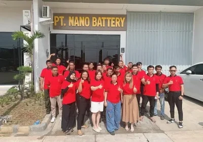 Celebrating 2 Years: JREPower Indonesia Production Base AnniversaryJanuary 13, 2026Today, JREPower (Shenzhen JREPower Tech Co., Ltd.) grandly celebrated the 2nd anniversary of its production base establishment in Jakarta, Indonesia. The milestone event gathered local government...view
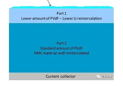 Understanding the Impact of High and Low Temperatures on Lithium Battery PerformanceMarch 31, 2026Lithium iron phosphate batteries and ternary lithium batteries in lithium batteries have the advantages of high energy density, wide operating temperature range, long cycle life, and safety and reliab...view
 Low & High Voltage Ride-Through: Why They Are Essential Stabilization Requirements for New Energy EquipmentJuly 22, 2026As large-scale PV and wind power connect to the grid, new energy sources are gradually replacing traditional generation, becoming the primary power supply unit of the power system. The grid is like a ...view
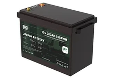 Classification and Characteristics of Lithium BatteriesMarch 31, 2026Lithium-ion batteries are characterized by their high energy density, lightweight design, lack of memory effect, and environmental friendliness. They are widely used in electric vehicles, energy stora...view
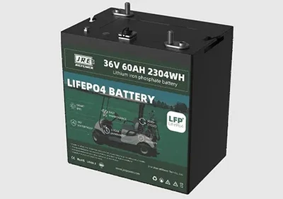 Golf Cart Battery Pack Upgrades (2026): How Lithium Helps Resorts and Courses Go Greener — And Look Better Doing ItJune 16, 2026For modern resorts and golf courses, sustainability is no longer a nice-to-have. Environmental compliance pressure is rising across hospitality and leisure sectors, and brand reputation increasingly d...view
 EN
EN